Thursday, July 28, 2016


WELCOME!!


Engr. Jay S. Villan, M. Eng.
Circuits 1 Professor

Saturday, July 23, 2016

Nodal Analysis

You have now learned about the laws pertaining to the basic circuit. As you dwell with more schematic figures of the various circuits, you are not just going to identify or calculate easily the voltage, current, power etc.

You will be dealing with more elements, more branches, more nodes, more loops and more brain-breaking problems. But all of these may be lessen turmoil may be lighten if you have understood very well the concepts of the Ohm’s Law and Kirchoff’s Current and Voltage laws(KCL and KVL) from the previous entries prior to this one.

Expected that you are now prepared to apply these laws to develop two powerful techniques for circuit analysis namely:
Nodal Analysis which is based on a systematic application of Kirchoff’s Current Law (KCL) and
Mesh Analysis which is based on a systematic application of Kirchoff’s Voltage Law (KVL). These two techniques are too significant and the students must not miss to dig deeper. Therefore, students are encouraged to pay much careful attention to this topic.
First analysis to be tackled is the Nodal Analysis.

NODAL ANALYSIS WITHOUT VOLTAGE SOURCE

This analysis provides a general procedure for analyzing circuits using node voltages as the circuit variables. It is more convenient to choose node voltages instead of element voltages and  it reduces the number of equations that must solve simultaneously. MAKES YOU NOT TOO CRAZY!!!

In nodal analysis, we are interested in finding the node voltages. Given a circuit with n nodes without voltage sources, here are the steps to take to determine Node Voltages.
  1.  Select a node as the reference node. Assign voltages v1, v2, … vn-1, to the remaining n-1 nodes. The voltages are referenced with respect to the reference node.
  2.  Apply KCL to each of the n-1 nonreference nodes. Use Ohm’s law to express the branch currents in terms of node voltages. (It is n-1 because you have to subtract 1 which refers to the reference node which has zero V already. So you just have to focus for the remaining nodes)
  3. Solve the resulting simultaneous equations to obtain the unknown node voltages.
The number of nonreference nodes is equal to the number of independent equations that you will derive.

Let us now talk furthermore about each step.

ON FIRST STEP:
Selecting reference Node or datum node is the first step in this analysis. The reference node is commonly called the ground and it is assumed to have a zero voltage. Commonly, we use the earth ground (a) or (b).

Keep in mind that Node 0 is reference node(v=0), while nodes 1 and 2 are assigned voltages v1 and v2. Always bear that node voltages are defined with respect to the reference node.


ON SECOND STEP:

Apply KCL to each nonreference node in the circuit. We advised you to redraw the circuits and put labels on each node with current and voltage labels. This is to avoid putting too much information on the same circuits and this will ease your CRAZINESS!!!

After this, sum up all currents i1, i2, i3 through their corresponding resistors R1, R2, R3,respectively.

At node 1, applying KCL gives     I­1=I2+i1 + i2

At node 2,    I­1+I2 = i3

We can now apply Ohm’s Law to express the unknown currents i1, i2 and i3  in terms of nodes voltages.

The key idea to bear in mind is that, since resistance is a passive element, by passive sign convention, current must always flow from a higher potential to a lower potential.
*Current flows from a higher potential to a lower potential in a resistor.

To be precised, this principle is set to be

I= vhigher - vlower
                R
  1. i1= v10
                  R1
  1. i2= v1v2
                    R2
  1. I3= v2 – 0
                   R3

Substitute all of the equations a, b, and c to the equations of node 1 and node 2.

After that, you have to simplify for you to take it easy for using Cramer’s Rule. (You are probably 3rd year or 4th year now, so we expect you to have knowledge about Cramer’s Rule)

Get the determinant first of the matrix coming from the equations on node 1 and node 2. (delta)

After getting the determinant, divide the delta1 from the delta. So as for the delta2 to get the v1 and v2.


NODAL ANALYSIS WITH VOLTAGE SOURCE

Let's consider that the voltage can affect the nodal analysis. Using this circuit, we can have two possibilities.

CASE 1
If a voltage source is connected between the reference node and a nonreference node, we simple set the voltage at the nonreference node equal to the voltage of the voltage source. In the figure, for example,

V1= 10 V
Thus , our analysis is somewhat simplified by this knowledge of the voltage at this node.

CASE 2
If the voltage source(dependent or independent) is connected between two nonreference nodes form a generalized node or supernode, we both now apply KCL and KVL to determine the node voltages.
where a  supernode is  formed by enclosing a (dependent or independent) voltage source connected between two nonreference nodes and any elements connected in parallel with it.

In this figure, nodes 2 and 3 form a supernode. We analyze a circuits with supernodes using the same three steps from behind but supernodes are just treated the other way on this matter. This is because KCL is essential component of nodal analysis which required knowing the current through each element. But there’s no way to know the current through a voltage source ahead. So, KCL must be satisfied at a supernode.
i1 + i4= i2 + i3

But how can you fill the i’s?

Remember the    I= vhigher - vlower      
                                                         R
You may apply it here. So,
v1 v2   +   v1 v2    =   v2 – 0  +   v3 –0   
   4                  2                 8             6
           
 To apply Kirchoff’s voltage law to the supernode in the figure, we redraw the circuits and make a loop in clockwise direction. This will give you
-v2   + 5 + v 0     to  v2  ­- v=  5  

We now obtain the node voltages. Note the following properties of a supernode:
  1. The voltage source inside the supernode provides constraint equation needed to solve for the node voltages.
  2. A supernode has no voltage of its own.
  3. A supernode requires the application of both KCL and KVL.


Example:


LEARNING/SUMMARY
  • Here we go now this one of the complicated topics that we have encountered. We do not want you to suffer like how we had it. You are now dealing with your confused mind. The best tip we can offer is to really familiarize all the topics prior to this one because this is also one of the applications of the basics.
  • Maybe at first you get a hard time, but practicing exercises are very useful.

Wye-Delta Transformation


Wye-Delta Transformation

One of the most confusing factors in circuit analysis is the resistors. Instances are often introduced in circuit analysis when you find a hard time in determining if the resistors are connected in series or parallel. 

1
Fig. 2.1

As you can see, there's a bridge circuit in Fig 2.1. How are you going to combine
R1 through Rwhen the resistors are neither in series nor parallel?

This problem can be simplified by using three-terminal equivalent networks. These are the wye(Y) or tee(T) network  shown in Figure 2.2 and the delta(∆) or pi (Π) shown in Figure 2.3. These networks occur by themselves as part of a larger network.


2
Figure 2.2 
(a) Y , (b) T 

3
Figure 2.3
(a) ∆ , (b) Π

Our main goal here is how to identify them when they occur as part of the network and how to apply wye-delta transformation or vice-versa to analyze the given network.

DELTA to WYE TRANSFORMATION

If a circuit contains a delta (∆,Π) configuration, it is more convenient to work with wye network. In short, transform it to Wye(Y)  to find its equivalent resistance.
In layman’s term, so that you can easily remember Delta to Wye conversion, the word “Wye”  always implies a number just like in algebra. And the resistor values are given already labeled as, Ra, Rb, Rc . Therefore, since you are to transform it to wye, the equivalent to be looked for is R1, R2, R3 .

In this case, let n be the number of resistor to be looked for as you transform delta to wye network.

The formula will be Rn= the value of the resistors on the two  adjacent sides
                                                       Summation of all the resistors given

It does not follow a direction or a pattern. What you have to remember is our layman’s general formula for this conversion since we have noticed that it is only applicable for delta to wye conversion.

 Example: 
 Use Figures 2.2 and 2.3.
4real

Transformation looks like this.
6


WYE to DELTA TRANSFORMATION

6
If a circuit contains a Y (Y, T) configuration, it is more convenient to work with delta network. In short, transform it to Delta (∆) network to find its equivalent resistance.
In layman’s term, so that you can easily remember Wye to Delta conversion, the word “Delta” gives you clue that the resistor to be solve is letters namely Ra, Rb, Rc . And the resistor values are given already labeled as, R1, R2, R3 . This is opposite from the first conversion method(Delta to Wye).

 Therefore, since you are to transform it to delta, the equivalent to be looked for is Ra, Rb, Rc .

In this case, let n be the letter of resistor to be looked for as you transform wye to delta network.

The formula will be Rn= the summation of the products of two resistors in order
                                                                        the opposite given Y resistor

5
The numerator in the formula gives you a pattern where the products of (R1 xR2), (R2 xR3), and (R3 xR1) are summed up. What you have to remember is our layman’s general formula for this conversion since we have noticed that it is applicable for wye to delta conversion.

OR

Rn= (R1 xR2)+(R2 xR3)+(R3 xR1)

                  Ropposite of Rn


LEARNING/SUMMARY

  • That in making the transformation, you do not take anything out of the circuit or put anything new. You are merely  substituting different but mathematically equivalent three-terminal network patterns to create a circuit in which resistors are either in series or in parallel, allowing you to calculate Req if necessary.

  • We, the bloggers, we also had and even having a hard time in transforming a complicated circuit since there is a lot of elements involved. So, as we advice, in redrawing circuits, observe first and choose the proper transformation as we have provided figures above as you guide.


Friday, July 1, 2016

Series and Parallel Resistors (Voltage and Current Division)

Series Parallel Animation
Review: Spotting Series and Parallel combinations
1.PNG

Series Resistors ⇒ same current flowing through them.

⇒ 1 path

The resistors in series could look like a V (a). They could look like an L (b). They could look like a stepwise function (c). It doesn’t matter what it looks like; if the resistors are connected at one end, it is in series.
Series Example

Series Resistors & Voltage Division


1.PNG
  • v1= iR1 & v2 = iR2
KVL:
  • v-v1-v2=0
  • v= i(R1+R2)
  • i = v/(R1+R2 ) =v/Req
  • or v= i(R1+R2 ) =iReq
  • iReq = R1+R2

VOLTAGE DIVISION FORMULA

Before:
v1 = iR1   &   v2 = iR2
i = v/(R1+R2 )
Thus:

v1=vR1/(R1+R2)

v2=vR2/(R1+R2)


To solve for Req:
Req = R1+R2 ...


Parallel Resistors & Current Division

Parallel Combinations
Now it gets a bit trickier. Are the resistor leads connected at two ends? Sometimes it’s very easy to see, like these nice block-y circuits.
Parallel Behaved
Sometimes, though, you get things that look like this.

When this is the case, shorten the wires.
Parallel Animation
Do the resistors end up side-by-side and connected at both ends? Then they are connected in parallel, with the current being split between the junctions that are in parallel.
For more info. visit: https://craftsandcircuits.wordpress.com/2014/06/19/visualizing-circuit-analysis-with-gifs/


Parallel Resistors ⇒ common voltage across it.

⇒ Still equal

2.PNG
  • v = i1R1 = i2R2
  • i   = i1+ i2
= v/R1+ v/R2
= v(1/R1+1/R2)
=v/Req
  • v  =iReq
  • 1/Req = 1/R1+1/R2
  • Req = R1R2 / (R1+R2 )

CURRENT DIVISION FORMULA

Before:
v = i1R1 = i2R2
v=iReq = iR1R2 / (R1+R2 )
and i1 = v /R1  &  i2 =v/ R2

Thus:

i1= iR2/(R1+R2)

i2= iR1/(R1+R2 )

To solve for Req:
Req = 1/R1+  1/R2 ...  1/Rn


Conductance (G)

Series conductance:

1/Geq = 1/G1 +1/G2+…

Parallel conductance:

Geq = G1 +G2+…


Now putting all this together…
Remember, orientation does not matter. We’ve been conditioned by nice, predictable circuit diagrams to think of series and parallel circuits in very limited forms, be it as a straight line or as a block-y succession of resistors. However, this will clearly not be the case all the time.
What we should appreciate is the basics. Connected on one end, series. Two ends, parallel. Resistor leads touching, short circuit. Because no matter what the complexity of the circuit is, these simple rules work every time.
Going back to the nasty circuit in the beginning…
(Assume that all unmarked resistors are 1 ohm.)
Reduce and Return -1
Source: https://craftsandcircuits.wordpress.com/2014/06/19/visualizing-circuit-analysis-with-gifs/


LEARNING/SUMMARY
  • In series circuits, you SHOULD use voltage division to find the desired unknowns.


  • In parallel circuits, you SHOULD use current division to find the desired unknown.


  • If the circuit is complicated, always be conscious and observe your steps when you are minimizing your circuit without disobeying the rules of parallel and series circuits.


  • ALWAYS BE AWARE AND DO NOT HASSLE YOURSELF.

Nodes, Branches & Loops

  • Elements of electric circuits can be interconnected in several way.
  • Need to understand some basic concepts of network topology.
    • Branch(es)⇒ Represents a single element. (ex: voltage,resistor & etc.)
    • Node(s)⇒ Meeting point between the two or more branches.
    • loop(s)⇒ Any closed path in a circuit.

example(1):

  • How many branches and nodes for the following circuit?

nodes

Answer: There were 5 branches and 3 nodes.

example(2):

There were:no
5 branches
  • 1 voltage source
  • 1 current source
  • 3 resistors
3 nodes
  • a
  • b
  • c

example(3):

  • How many branches, nodes and loops for the following circuit?
yeye
Answer: There were 7 branches, 4 nodes, and 10 loops.


Kirchhoff's Current Law (KCL)

  • The algebraic sum of current entering/leaving a node (or closed boundary) is zero.
  • current enters- positive (+)
  • current leaves- negative (-)
  • ∑ current entering = ∑ current leaving

example KCL(1):

  • Given the following circuit, write the equation for currents.
yeye2


example KCL(2):

  • Current in a close boundary.
yeye3


example KCL(3):

  • Use KCL to obtain currents i1, i2, and i3 in the circuits.
yeye4
Answer:
A= 1A+i1=2A+10A
i1=12A-1A
i1=11A
B= 3A+2A=1A+i2
5A=1A+i2
i2=4A
C= i3+10A=11A
i3=11A-10A
i3=1A

Take note:

Series=add up voltage

Parallel=equal voltage

Kirchhoff's Voltage Law (KVL)

  • Applied to a loop in a circuit.
  • According to KVL→ The algebraic sum of voltage (rises or drops) in a loop is zero.
KVL
From positive → negative
+Vs-V1-V2-V3=0


example KVL(1):

  • Use KVL to obtain v1, v2 and v3.
ex kvl1
Answer:
+20+25-10-v1=0
V1=35v
+10-15+v2=0
v2=-10+15
v2=5V
+v1-5-v3=0
35-5-v3=0
v3=30V

example KVL(2):

  • Use KVL to obtain v1 and v2.
ex kvl 2
Answer:
+10v+12v+6v-v1-v1=0
28v-2V1=0
28V/2=2V1/2
V1= 14V
+V2-12V-10V=0
+12V-22V=0
V2= 22V

example KVL(3):

  • Calculate power dissipated in 5Ω resistor.
yeye5
Answer:
P= iv = i²R = v²/ R
V 5Ω = 5i
45-10i + 3vo – 5i =0
vo = 10i
45-Vo + 3vo -5i = 0
i = Vo/10
45-Vo +3vo -5 (Vo/10) = 0


LEARNING/SUMMARY
  • In determining the nodes, always look for the intersection or cross section of two elements.
  • Branches are also called as element. So, do not get to far and do not make hard on yourself.
  • Loops are any closed path in a circuit.
  • At our first encounter, we had suffered like a chaos in our mind. But this is what we tell you, our learners, always circle round in clockwise and use the sign upon exit. This is applicable KVL. But you can choose counterclockwise as well. But you know, just like the clock, it goes from left to right the reason why you read the clock rightly.
  • We also advice you take layman's term for yourselves but make sure you have understood the fundamental concepts behind each thing. Just like in KCL, positive is equals to negative; where enters to you life, you will be positive. And so as if people leave you behind, you will be negative already.  But you will still be equal in a way that people may leave you but there are people who will come to you.

Saturday, June 25, 2016

Basic Laws (OHM'S LAW)

Ohm's Law - Relationship between current and voltage.
Ohm's Law

⇒ Here , when the Potential difference of 0 voltage is applied the ammeter in the circuit reads 0 amps , when it is increased to 5 voltage the ammeter reads 1 amps which is verified using the formula   I = \dfrac{V}{R} 
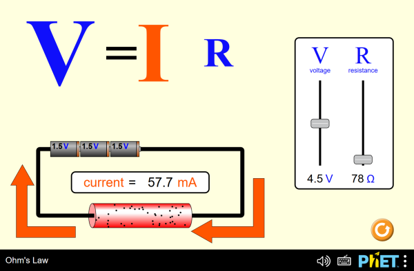
and so on , which is in accordance with the ohm law which states that the current flowing the circuit is directly proportional to the potential difference applied when the resistance is kept constant....Read more https://electronicspani.com/ohms-law/


  • The voltage across an element is directly Proportional to the current flowing.
    • V∝i
Thus: v=iR and R/i
Where: R=resistor ⇒ Has ability to resist the flow of electric current.
Capture

Take note:
  • Resistors has no polarity
  • Not flows - to +


  • The value of R :: Varies from 0 to infinity
  • Extreme values == 0 and infinity
  • Only linear resistors obey ohm's law
undefined
The transmission lines, the top one terminated at an open circuit, the bottom terminated at a short circuit. Black dots represents electrons, and the arrows show the electric field.

[gallery ids="283,284" type="rectangular"]


CONDUCTANCE

⇒ The ability to conduct electric current flow.
  • unit (mho) or (siemens)
  • symbol S
  • Reciprocal of the resistance R (G= 1/R)

POWER

pwer form.PNG
  • R and G are positive quantities, thus power is always POSITIVE.
  • R absorbs power from the circuit → PASSIVE ELEMENT

EXAMPLE 1

  • Determine voltage (v), conductance (G) and power (p) from the figure below.
ex.1
Solution:

For voltage:

v=iR
=(2*10^-3)(10*10^3)
v=20V

For Conductance:

G=i/R
=1/10*10^3
G=1*10^-4

For Power:

P=t^2R
=v^2/R
=(2*10^-3)^2 (10*10^3)
=0.04 w
=40mW
=(20)^2/10*10^3
P=0.04 w

EXAMPLE 2

  • Calculate current i in figure below when the switch is in position 1.
  • Find the current when the switch is in position 2.
ex 2
Solution:
(a) i = 3/100 = 30 mA
(b) i = 3/150 = 20 mA


LEARNING/SUMMARY
  • Everything around us is connected or related with each other. So, therefore, in dealing with circuit analysis, everything is also related. One element might be directly proportional. It could be that another element is inversely proportional to the other. But the point is, if one has been measured or calculated mistakenly, everything will be reversed to be wrong.

  • So, therefore, if you have not understood the basics, it would be hard for you to go through. So, go back to the previous lessons and come back to deal with this topic.


TRY THIS! ↓↓↓

https://phet.colorado.edu/sims/html/ohms-law/latest/ohms-law_en.html
Click to Run

Wednesday, June 22, 2016

Introduction

Basic Concept (Chapter 1)
Any engineering courses related with electricity must study and understand the fundamentals of electric circuits as students enter in their major subjects.

Fundamentals of Electric Circuits

Introduction

Electric circuit and electromagnetic theories are two fundamental theories upon which all branches of electrical engineering are built.
WHY DO WE NEED TO STUDY "BASIC ELECTRIC CIRCUIT"?
  •  This is because everything starts with the BASICS. We cannot jump up to the hardest fields without dwelling with the penny matters. Basic electric circuit is the most important course for electrical engineering students and even electronics and computer engineering courses education.
  • This is valuable for students like us who are specializing in other branches of the physical sciences because circuits are good model for the study of energy systems in general, and because of the applied mathematics, physics, and topology involved.


What is Electric Circuit?

download
Fig. 1

An Electric Circuit is an interconnection of electrical elements. Electric circuit theory and electromagnetic theory are the two fundamental theories upon which all branches of electrical engineering are built.
Its function is to transfer energy from one point to another or from one element to another element.
 Fig. 1 This is an example of a simple Electric Circuit. It has battery, switch and the bulb. When you turn on the switch with a closed loop the current flows and the bulb will light up.


BASIC ELEMENT

Charge- q(t)

It refers to the basic quantity in an electric circuit.
ELECTRICAL PROPERTY OF MATERIALS
  • Exist (Electron) which is negative and (Proton) positive
  • Measured in Coulombs (C)C
  • One electron has a charge of -1.602 * 10 ^-19 C

Current- i(t)

  • It refers to the charge flow rate
  • It is measured in Ampere (A)
  • 2 types: DC (Direct Current) and AC (Alternating Current)
dcacvis

Voltage- v(t)

  • It refers to the charge rate of doing work
  • Energyrequired to move a unit charge through an element
  • Measured in volts (V)

Power- p(t)

  • It refers to time rate of doing work
  • Measured in watts (w)
Power can be absorbed or supplied by circuit elements
  • positive power- element absorbs power
  • negative power- element supplies power
  • 'sign' determined by voltage and current
  • An ideal circuit is ΣPsupplied + ΣPabsorbed = 0

Energy

It is the capacity to do work


Circuit Elements

  • An element is the basic building block of a circuit
  • Electric circuit is interconnecting of the elements

      Types of Elements:
  • Active elements- capable of generating energy
  • Passive elements- absorbs energy


Source

  • Independent Source- does not depend to other elements to supply voltage or current.
  • Dependent Source- Depend to other elements to supply Voltage or Current.


Example Exercises (1)

  • Determine the current flowing through an element if the charge flow is given by:   q(t) = (9t² +2t-2) C
Solution:
q(t)= 9t²+2t-2  C
dq/dt= 18t+2
i(t)=dq/dt =18t+2

  • Find the charge q(t) flowing through a device if the current (i(t)) = (2t + 5) mA and q(0)=0
Solution:
i= dq/dt                                                  q(0)=0
∫dq= ∫i dt                                               q(0)= t²+5t+C =0
q= ∫i dt                                                           =0²+5(0)+C
q= ∫ (2t+5) dt                                                =0
q(t)= t²+5t+C                                                   Therefore, the charge is 0.


  • The change entering a certain element is shown. Determine the current at:
(a) t = 1 ms
(b) t = 6 ms
(c) t = 10 ms
exercise
Solution:
(a) At t = 1ms, i= dq/dt
=80/2
=40A
(b) At t = 6ms, i= dq/dt
=0A
(c) At t = 10ms, i= dq/dt
=80/4
=20A


LEARNING/SUMMARY
  • In analyzing or dealing with circuits, it is really better for us to know what are the concepts under every thing. We must know how everything works, how each element affects the whole circuits and how conscious we should be in taking part of analyzing the circuit. Because if we fail to do this, we will be failure at all level regarding circuit analysis.


  • It is important to know the basic elements of the circuit because it is always the best to start with the basics since it is the foundation in solving or dealing problems as we go through our journey to be electrical and electronics engineers.


  • Each element is co-related with one another. They might be directly proportional or inversely proportional with each other.